
Provincial College Innovation Project · Intelligent Networked Monitoring Equipment for Drug Liquid Effectiveness Detection
Affiliated with the provincial innovation project "RF Micro-sensing Test System for Drug Effectiveness," using GPS positioning data as a demonstration payload, it completed the full-stack data link from the STM32L0 device side, CT02 4G LTE module to the MQTT IoT platform, constructing a complete IOT-MQTT data loop. The platform side is based on Node.js integrating Aedes Broker, Express, Socket.IO, and SQLite; the device side uses a DMA+IDLE interrupt mechanism to achieve highly reliable AT firmware daemon, paired with a TJC serial screen and low-power sleep strategy, balancing on-site interaction and battery life requirements.
Abstract
This project is affiliated with the Provincial College Student Innovation and Entrepreneurship Training Program project "RF Micro-sensing Test System for Drug Effectiveness." The project aims to achieve non-contact detection of drug liquid components using RF micro-sensing technology, and report sensor analysis results in real-time to a remote platform via the IoT system, thereby enhancing the intelligence level of drug safety supervision and drug liquid quality control. The work described in this report serves as the IoT engineering demo of the project. Currently using GPS positioning data as a demonstration payload, it has completed the full-stack data link from the STM32L0 device side, CT02 4G LTE module to the MQTT IoT platform, constructing a complete IOT-MQTT data loop.
On the platform side, this project is based on the Node.js development environment, integrating Aedes MQTT Broker, Express Web service, REST API, Socket.IO real-time channel, and SQLite local database, implementing functions such as device access authentication, topic parsing, GPS data identification, status persistence, command queue and ACK loop, offline command retransmission, and Web console real-time visualization. On the device side, the STM32L0 microcontroller uses USART2 DMA circular reception and IDLE interrupt drain mechanism to build a reliable CT02 AT firmware daemon, completing tasks such as MQTT connection maintenance, GPS cold start and positioning quality filtering, periodic reporting, and parsing and execution of platform downlink commands; simultaneously, it drives the TJC serial screen via USART1 for local status display and parameter configuration, and uses PA4 external interrupt and PA5 screen power control to switch between sleep and running states, balancing on-site interaction and low-power requirements.
The significance of this project lies in: at the current stage, GPS data has been used to verify and solidify the end-to-end IoT communication architecture, platform protocol specifications, device-side daemon mechanism, and uplink/downlink command closed-loop process; after subsequent calibration of the RF micro-sensor, only the device-side reporting payload needs to be replaced from GPS coordinates to drug liquid component analysis data, allowing direct reuse of the existing MQTT topic system, platform parsing logic, and Web visualization framework, achieving remote real-time monitoring and historical traceability of sensor analysis results, providing a directly migratable engineering foundation and verification platform for achieving the overall project goals.
Project Background and Overall Architecture
The MQTT IoT platform of this project is an integrated IoT server. The operating device is a high-performance personal idle laptop (CPU: Intel Core i5-13420H, OS: Linux Ubuntu 24.04). It uses FRP intranet penetration technology to configure and connect ports 6010/6011 on this machine with corresponding ports on an Alibaba Cloud server (IP: 120.26.111.75, bandwidth 200 Mb/s), and the functionality and effectiveness have been verified through actual 4G LTE/GPS device (Daxia Longque AT firmware, model: CT02) experiments.
In the MQTT Node.js process designed by this project, the MQTT Broker, HTTP Web service, REST API, Socket.IO real-time channel, and SQLite local database are started simultaneously. The device side connects via the MQTT protocol, the browser side accesses via HTTP and WebSocket, and the platform backend performs data parsing, status maintenance, command issuance, and real-time refresh between the two. During platform operation, the Aedes library creates the MQTT Broker, listening on port [20]; Express creates the Web service, listening on port [21]; Socket.IO is mounted on the same HTTP service to push device online, offline, GPS updates, and command ACK to the browser in real-time; the SQLite database access code is responsible for persisting devices, messages, command tasks, and offline command queues. During deployment, the PM2 persistent daemon configuration code is responsible for service auto-restart, log writing, and runtime environment parameter loading. 127.0.0.1:6010 Port; Express creates a web service and listens on 127.0.0.1:6011 Port; Socket.IO is mounted on the same HTTP service to push device online/offline status, GPS updates, and command ACKs to the browser in real time; the SQLite database access code is responsible for persisting devices, messages, command tasks, and offline command queues. During deployment, the PM2 persistent daemon configuration code handles automatic service restart, log writing, and runtime environment parameter loading.
| Layer | Implementation Module | Main Responsibilities |
|---|---|---|
| Service Startup and Integration | Main Service Startup Code (.JS) | Create Aedes Broker, Express service, Socket.IO channel, handle MQTT events, REST routes, command queues, and scheduled tasks |
| Configuration Reading | Platform Parameter Configuration Code (.JS) | Read MQTT port, Web port, account password, offline TTL, command timeout, AMap Key, and database path from environment variables and default values |
| Data Persistence | SQLite Data Persistence Code (.JS) | Initialize SQLite table structure, save device status, message records, GPS tracks, command tasks, and offline pending commands |
| Protocol Parsing | MQTT Protocol Parsing Code (.JS) | Parse [37] topics, JSON, GPSST text, NMEA messages, status messages, and [38] Frontend Page ct02/... Topics, JSON, GPSST text, NMEA messages, State messages, and requestId |
| Frontend page | Console Page Structure Code (.HTML) | Define four main views: device table, GPS control, map track, and message stream |
| Frontend Logic | Browser Interaction Logic Code (.JS) | Call REST API, listen to Socket.IO events, render devices, command results, message lists, and GPS tracks |
| Style and Deployment | Style and Process Configuration | Provide console interface styles, as well as PM2 process daemon, log, and environment variable configuration |
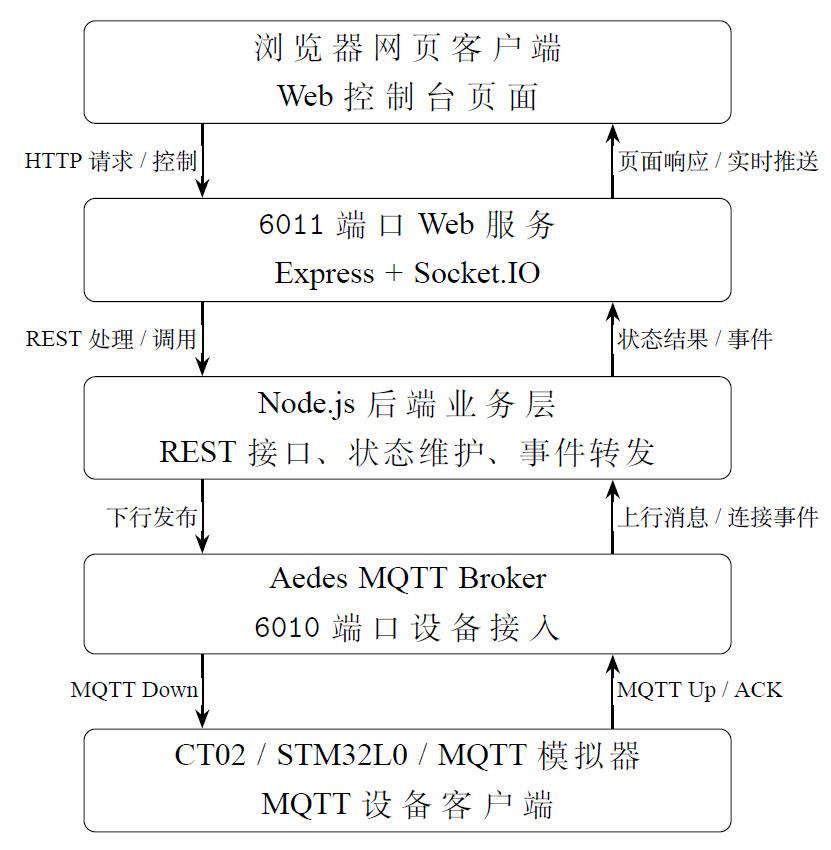
MQTT Server Platform Design
Basic Principles of MQTT Protocol
MQTT (Message Queuing Telemetry Transport) is a lightweight application layer communication protocol designed for IoT scenarios, typically running over TCP connections. Its design goal is not to transmit large files or complex web content, but rather tocomplete the transmission of device status, sensor data, and control commands with minimal protocol overhead under conditions of limited network bandwidth, limited device computing power, and potentially unstable connections.Therefore, MQTT is commonly used in scenarios such as GPS trackers, environmental sensors, industrial data acquisition terminals, and remote control nodes.
The most important concept of MQTT is thepublish/subscribe model.Traditional HTTP communication usually involves a client actively requesting and a server returning a response; MQTT, on the other hand, treats both communicating parties as clients, with aBroker in the middle responsible for message forwarding.The publisher only needs to send amessage to a specific topic,and the subscriber only needs to declare which topics they are interested in. The two parties do not need to know each other's IP addresses, connection status, or specific numbers. This reduces coupling on the device side: when a device publishes GPS data, it does not need to directly connect to a web page, database, or other business programs;when a new subscriber is added to the platform, the device firmware does not need to be modified.。
The three basic elements in MQTT communication are the client, topic, and payload.A client can be a sensor device, backend service, debugging tool, or gateway program; a topic is used to describe the classification path of a message, commonly using slashes for hierarchy, for example factory/line1/temperature;The payload is the specific content carried under a topic,which can be JSON, plain text, binary data, or a device manufacturer'scustom format.The MQTT protocol itself does not specify the business structure of the payload;it is only responsible for passing the payload as the message body to the subscriber.Therefore, the specific field meanings, units, data validity, and command semantics must be defined by the upper-layer application protocol.
| Mechanism | Basic Meaning |
|---|---|
| Broker | MQTT message center, responsible for receiving client connections, maintaining subscription relationships, and forwarding published messages to matching subscribers |
| Topic | Message topic, describing the message category using a hierarchical string; subscribers can receive messages based on the full topic or wildcard rules |
| Payload | Message payload, treated by the protocol layer only as a byte sequence; the actual format is agreed upon by the business system itself |
| QoS | Quality of Service level, including levels 0, 1, and 2, corresponding to at-most-once, at-least-once, and exactly-once delivery semantics respectively |
| Retain | Retained message mechanism, where the Broker can save the last retained message for a topic, allowing new subscribers to immediately obtain the current status |
| Keep Alive | Keep-alive mechanism, where the client periodically confirms with the Broker that the connection is still valid, used to detect abnormal disconnections |
| ClientID | Client identifier, used by the Broker to distinguish different connections, and can be combined with the session mechanism to restore subscriptions or state |
| Will Message | Will message, published by the Broker on behalf of a client when it disconnects abnormally, commonly used to notify other systems of device offline status |
Backend Runtime Design
The backend runtime design can be divided into six parts based on implementation responsibilities:Service startup and parameter assembly, MQTT access and identity constraints, protocol parsing, state and data persistence, command queue and ACK loop, scheduled maintenance and process daemon.With this division, the platform is not a simple MQTT forwarder, but an IoT server capable of saving state, tracking commands, determining online status, and driving web page refreshes in real time.
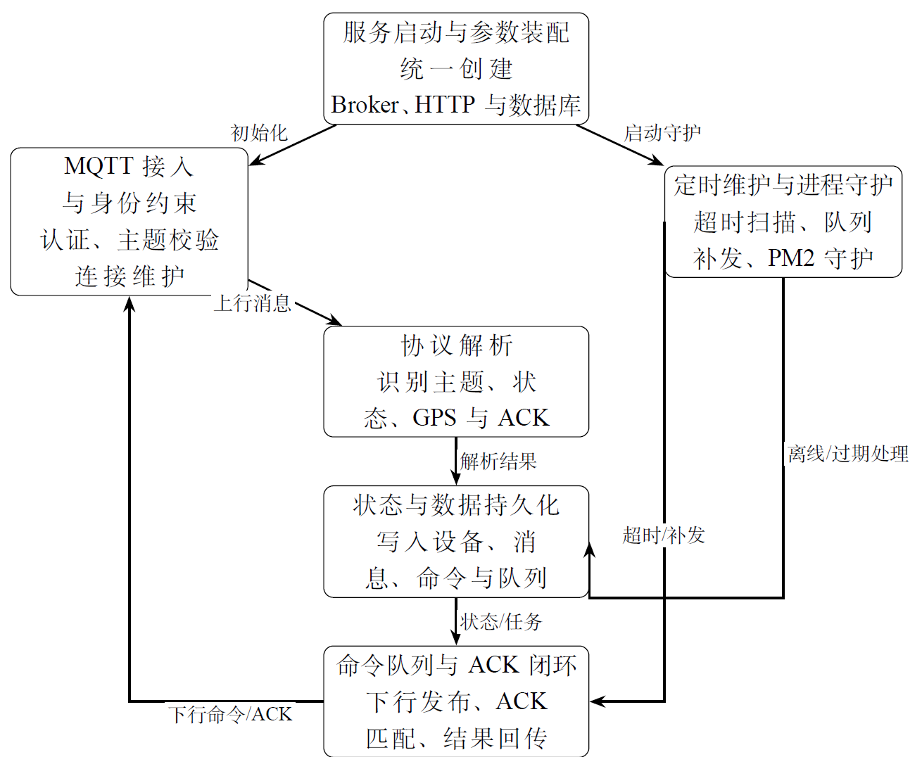
Service startup and parameter assembly:The main service startup code (.JS) is the unified entry point for the backend. It creates theMQTT Broker, HTTP service, REST routes, Socket.IO real-time channel, and SQLite access objectwithin the same Node.js process. Therefore, device communication, web page access, and database read/write do not require manual splicing of multiple independent programs. The platform parameter configuration code (.JS) is responsible forcentralizing runtime parameters to facilitate migration, open-sourcing, and debugging.Configuration values are preferentially taken from runtime environment variables; if absent, built-in default values from the project are used.
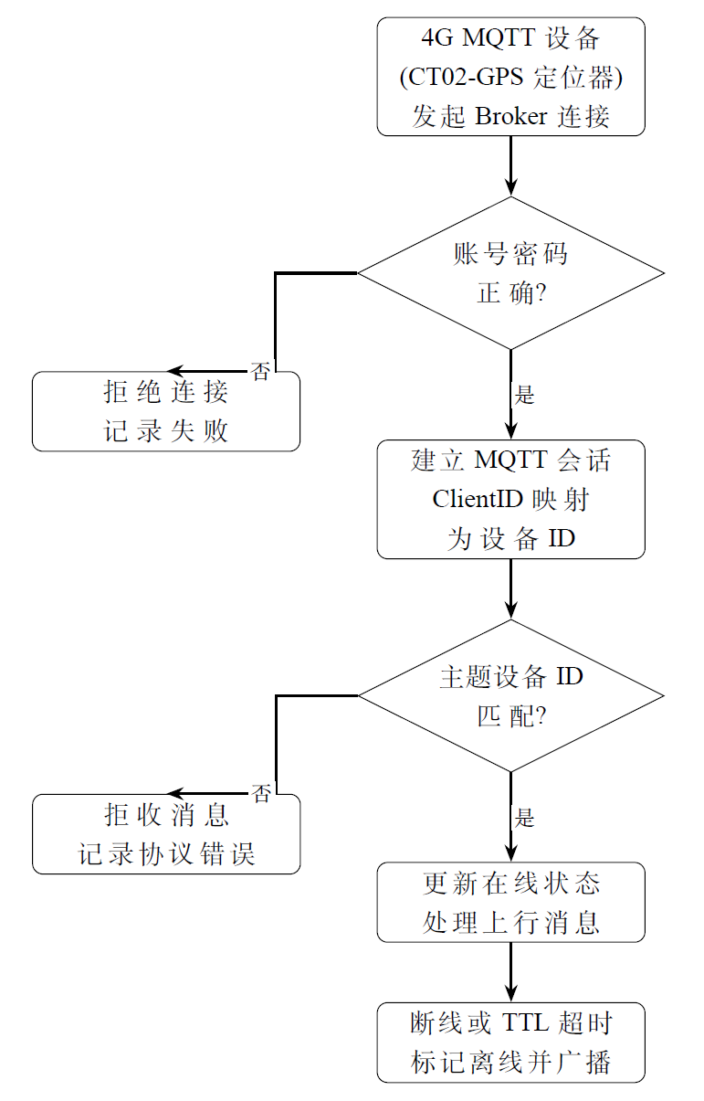
MQTT access and device identity constraints:The MQTT access module is implemented by the Aedes Broker. Devices need to submit a username and password when connecting; a session is only allowed to be established after successful authentication. After the session is established, the platform writes the MQTT ClientID as the device ID into the device state table, and records the IP address, online time, and connection count. When a device publishes a message, the platform also performstopic identity verification.According to the project convention, the topic format is ct02/deviceID/channel name, where the device ID must be consistent with the MQTT ClientID. This constraint prevents serial number conflicts between different devices and ensures that device records, message records, and command records in the database are always archived around the same device ID.
Protocol parsing and GPS data identification:The MQTT protocol parsing code (.JS) first processes the topic, then processes the payload. Topics that do not conform to the ct02/deviceID/channel name format are recorded as ordinary messages or protocol exceptions. After the payload enters the backend, it is first uniformly converted to a UTF-8 string, and then an attempt is made to parse it as JSON; if it is not JSON, identification continues according to the CT02 text format and NMEA sentences. GPS identification is the focus of this module: for JSON data, the platform preferentially reads the root field or the latitude, longitude, altitude, and positioning valid flag in the GPS object; for the +GPSST text directly output by the CT02 module, the platform parses the positioning status, satellite signal, longitude, altitude, and latitude; for NMEA messages, the platform is compatible with both RMC and GGA positioning sentences, and converts the degree-minute format to decimal degrees. Only when the positioning is valid and both latitude and longitude are legal values does the backend write the message as a GPS track point to the database and broadcast it. gps.update。
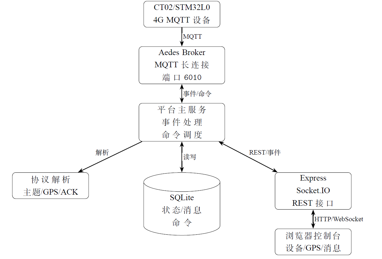
State Recording and Data Persistence: The SQLite data persistence code serves as the platform's "memory." The database mainly consists of four types of tables:device table, message table, command task table, and offline command queue table. Each time the platform receives a business message, it first updates the device's latest active time and then writes the message into the message table. If the message contains valid GPS coordinates, it also synchronously updates the last longitude/latitude and last positioning time in the device table. When the frontend queries the device list, it reads from the device table; when querying the message stream, it reads from the message table; and when querying the trajectory, it only reads message records with valid longitude/latitude. Thus, the three types of page data—device status, historical messages, and map trajectories—all originate from the same set of persistent records, avoiding inconsistencies between in-memory state and historical data.
Command Queue and ACK Closed Loop: The command dispatch moduleis composed of the REST interface, MQTT publishing logic, the command task table, and the offline command queue. After the browser submits a GPS control command, the backend generates or completes the command requestId, simultaneously fills in the timestamp, and incorporates the command into a unified task tracking workflow. Therefore, this part is not merely "sending an MQTT message" or a "fire-and-forget" approach like UDP; rather, it establishes a control chain around the full command lifecycle that is queryable, traceable, retransmittable, and capable of timeout determination.
The REST API is a standard HTTP request interface from the web page to the backend.POST /api/devices/:id/commands It is used to receive control commands submitted by the frontend: if the device is online, the command is immediately written into the command task and dispatched via the ct02/deviceID/down topic, and a response is returned deliveryMode=immediate; if the device is offline but queuing is allowed, the command is written into the offline command queue and a response is returned deliveryMode=queued; if the device is offline and queuing is prohibited, the interface directly returns a rejection result. After the device comes back online, the queue refresh logic searches for commands that have not expired and have not exceeded the retry limit, and republishes them in order of creation time. The ACK closed loop relies on requestId: after executing the command, the device publishes a response to the /ack channel. The backend extracts requestIdfrom the ACK content, then updates the ACK time, ACK content, and task status of the corresponding command task, and broadcasts command.ack. If no ACK is received before the command timeout, a scheduled task marks the command as timeout and notifies the frontend.
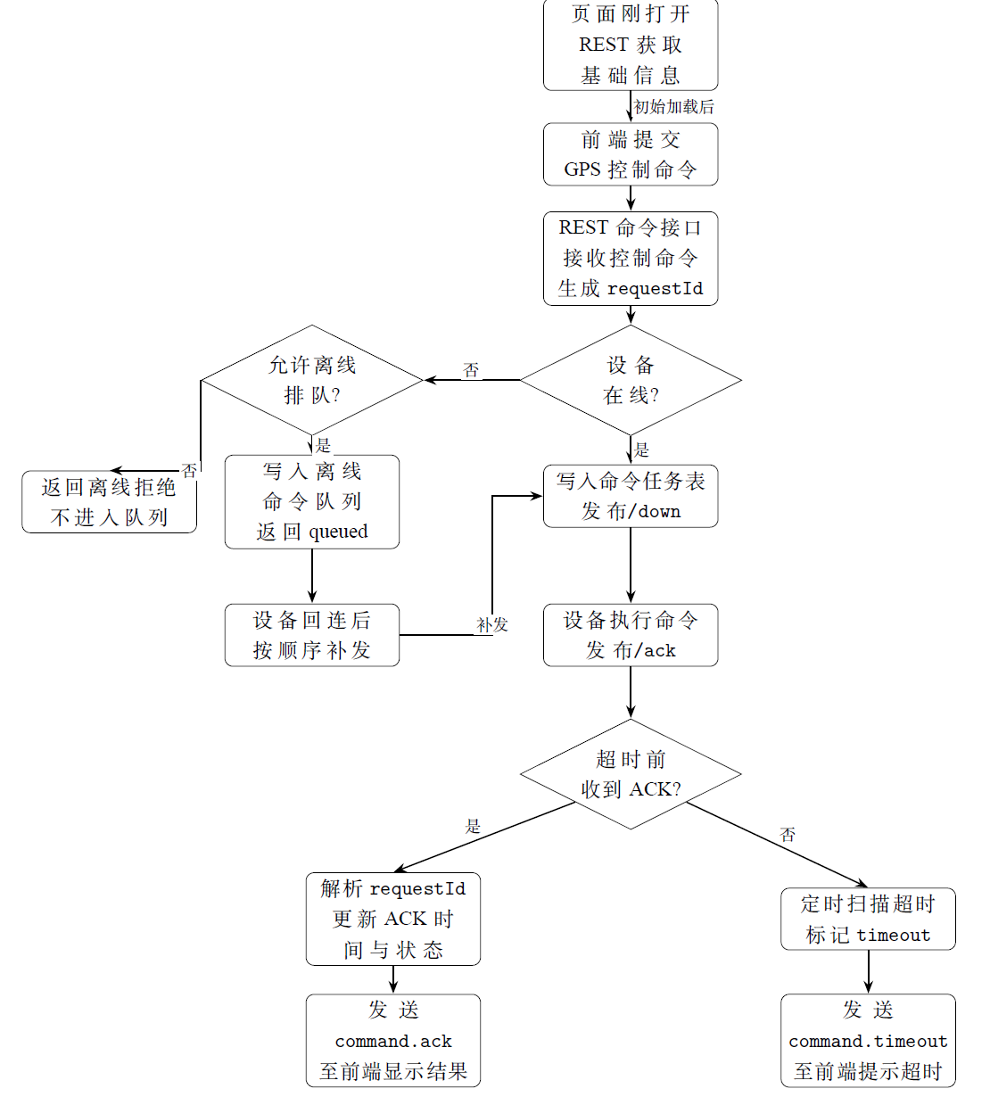
Real-time push, scheduled maintenance, and process daemonThe real-time push module is solely responsible for converting backend-generated status events into incremental notifications visible in the browser. After the backend receives events such as device online/offline, message storage, GPS updates, command sending, command ACK, command timeout, offline command enqueuing, and command expiration, it broadcasts them to the frontend via Socket.IO. The backend also includes three types of periodic maintenance tasks: command timeout scanning, offline queue scanning (re-sending and cleanup), and device online fallback scanning. The PM2 persistent daemon configuration code handles process startup, automatic restart, log output, and environment variable injection in the production environment, enabling the platform to run continuously on the server.
Frontend operating principle (Web Console)
The frontend Web Console serves as the browser-side human-computer interaction layer. It does not directly connect to port 6010 as an MQTT client; instead, it accesses the backend's organized device status, message records, GPS trajectories, and command tasks via the Web service. The core function of the frontend isto transform the backend's MQTT events, database records, and command statuses into viewable, filterable, and operable page modules.。
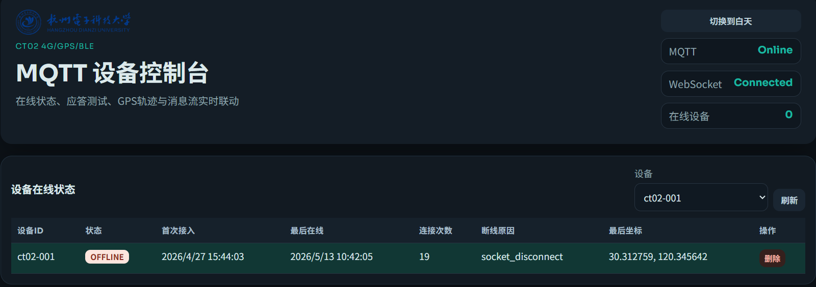
The page structure can be divided according to"status display, command input, trajectory display, and message auditing,"four functional categories. The top of the page displays the MQTT platform status, WebSocket connection status, and the number of online devices. The device online status area shows the device ID, online status, first connection time, last online time, connection count, disconnection reason, and last coordinates. The GPS control and command area encapsulates common gps.control actions into buttons and input fields. The GPS trajectory area renders the trajectory points returned by the backend on an AMap (Gaode Map) or a coordinate list. The message stream area displays the raw payload and JSON parsing results of uplink and downlink messages.
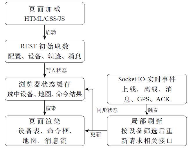
The frontend startup process is not a one-time static page display, but rather a process of"loading configuration, obtaining a snapshot, establishing real-time listening, and performing partial Socket.IO refreshes based on events."After the browser loads, app.js it first applies the theme settings, then requests /api/frontend-config to read the GPS control template, command timeout parameters, offline queue parameters, and map configuration. Subsequently, it initializes the map display capability, calls /api/devices to retrieve the device list, and, based on the currently selected device, continues to read messages, trajectories, and the actual reporting interval. After the initial snapshot is loaded, the frontend establishes a Socket.IO connection and listens for device, message, GPS, and command events broadcast by the backend. The advantage of this approach is that the page relies on REST APIs for the complete status upon first load, and thereafter primarily uses Socket.IO events to trigger partial updates, avoiding the need for users to manually refresh frequently.
The downlink control chain starts from page operations. After the user selects the target device in the device selector and clicks buttons such as "View GPS Status," "Enable GPS," "Disable GPS," "Capture Snapshot Now," or "Set Reporting Interval," the frontend generates a gps.control payload based on the template returned by the configuration API and sends it to the backend via the REST command submission interface. The backend decides whether to publish the command immediately or enqueue it in the offline queue, and returns the command task to the page. If the device is online, the backend proceeds to publish the command to the MQTT downlink topic. If the device is offline, the page displays a queued status. Subsequently, when the device returns an ACK or the backend determines a timeout or expiration, the Socket.IO event pushes the task status to the browser, and the command result box is updated accordingly.
The uplink display chain begins with device messages. After a CT02 or STM32L0 device publishes GPS or status data to an MQTT topic, the backend performs topic parsing, payload parsing, database writing, and event broadcasting. Upon receiving message.in , the frontend refreshes the message stream; upon receiving gps.update , it refreshes the trajectory and the actual reporting interval; upon receiving device.online/offline , it refreshes the device table. The web console adopts a design where "the REST interface provides the current state, Socket.IO provides real-time triggers, and the browser state manages current selections and partial rendering."


STM32L0 Serial Daemon, GPS-AT Firmware, and Display Design
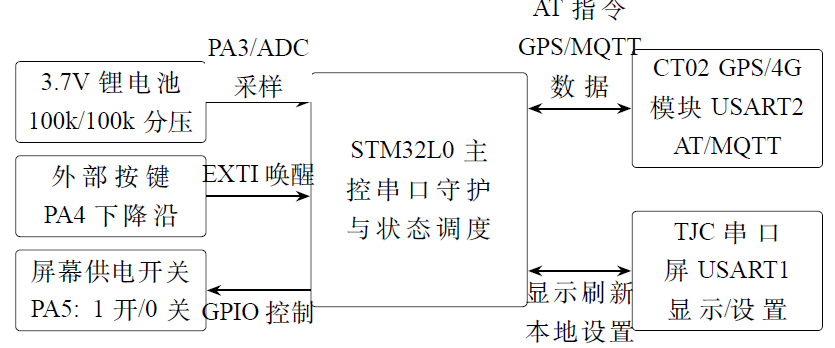
The STM32L0 program serves as the on-site gateway and local interaction unit. This STM32L0 project is centered around two serial ports: one is an AT command daemon channel for the CT02 GPS/4G module, responsible for cellular network connectivity, MQTT connections, GPS positioning, and uplink/downlink commands; the other is a display and local control channel for the TJC serial screen, responsible for synchronizing platform status, positioning intervals, and operational status to the screen, while also receiving local settings from the screen. In addition to these two serial ports, the system uses the PA3 on-chip ADC for lithium battery level detection, and implements a "sleep/run" state switch via the PA4 external interrupt and the PA5 screen power control pin.
In terms of program responsibilities, USART2 serves as the main data link between the device and the remote MQTT platform, while USART1 is dedicated solely to the local human-machine interface; the two do not share the same serial port. This separation prevents screen refreshes or local button operations from blocking the CT02 module's periodic GPS reporting, and also facilitates powering down the entire screen during power-saving states without affecting background positioning transmission.

Overall Interface and Module Division
| Interface | Connected Object | Main Function |
|---|---|---|
| USART2 PA2/PA15 | CT02 GPS/4G Module | Performs AT initialization, MQTT connection, subscription to downlink topics, GPS positioning control, and periodic reporting of positioning and status; uses DMA reception and idle interrupts to improve serial daemon reliability. |
| USART1 PA9/PA10 | TJC Serial Screen | Sends screen variable refresh commands to display platform address, reporting interval, battery/operational status, etc.; receives setting frames from the screen and maps them to the device's local control logic. |
| ADC PA3 | Lithium Battery Voltage Divider Sampling | Samples the voltage of a 3.7V single-cell lithium battery after division by two 100k resistors using 12-bit ADC, converts it to battery voltage, and estimates remaining capacity. |
| EXTI PA4 | External Button | Detects a falling-edge interrupt, triggering the device to enter a one-minute operational window from the power-saving state. |
| GPIO PA5 | Screen Power Supply Optocoupler Switch | Controls the screen power supply: output 1 indicates the screen is turned on, output 0 indicates the screen is turned off. |
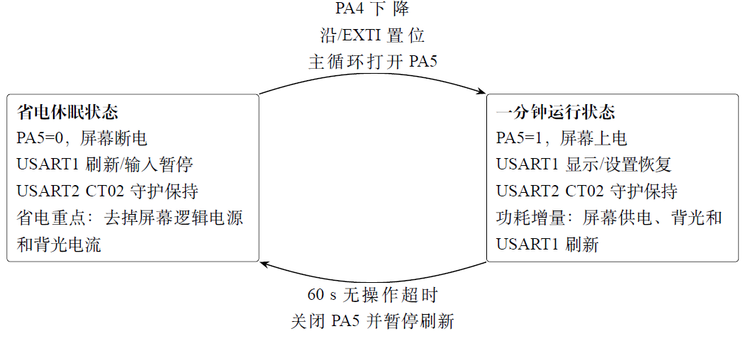
Power-Saving Design for Sleep/Operational States
After the overall interface division, the power-saving strategy of this device needs further elaboration. Here, "sleep" does not refer to putting both the STM32L0 and CT02 into deep power-down mode as a whole, but rather decoupling the local human-machine interaction from the backend communication link: when no on-site operation is performed, the screen power supply is turned off, USART1 screen refresh and screen input parsing are suspended; the USART2 daemon link where CT02 resides continues to operate, maintaining the MQTT connection, GPS positioning cache, and periodic reporting. The core of the above power-saving design is not to sacrifice the continuity of platform-side data, but to reduce the ineffective power consumption of the screen and local interaction during long-term standby.
The system divides the operational states intothe power-saving sleep state and the one-minute operational state.。Power-Saving Sleep StateDesigned for long-term unattended operation: PA5 outputs a low level, the screen power supply optocoupler is turned off, and the screen backlight and screen logic power no longer consume the main battery energy; in the main loop, USART1 display commands are no longer actively queued for transmission, nor does the system rely on the screen side to set frame completion for backend communication. Meanwhile, the USART2 CT02 daemon task continues to run periodically, with GPS sample caching, sustained MQTT connectivity, downlink topic listening, and automatic reporting logic remaining active.
One-Minute Operational StateDesigned for on-site inspection and temporary configuration. After the falling edge triggered by the PA4 button, the external interrupt only performs lightweight event flagging, while the actual state transition is completed in the main loop or scheduling function. Upon entering the operational state, PA5 outputs a high level,the screen is powered on again;the system records a timeout point one minute later, and resumes USART1 reception and parsing, screen variable refresh, and local setting processing.Within this one minute, the user can view the platform address, MQTT connection status, GPS coordinates, reporting count, battery status, and reporting interval via the HMI serial screen, and can also modify the positioning reporting period through the screen.If a PA4 button event is detected again during the operational state, the system does not need to reinitialize all peripherals;it only refreshes the one-minute operational window,ensuring the screen remains lit during continuous operation.
| State | Local Display and Interaction | Background Communication and Positioning | Main Power Consumption Characteristics |
|---|---|---|---|
| Power-Saving Sleep State | PA5=0: screen power-off; USART1 display refresh and screen input parsing are suspended; local user temporarily refrains from operation. | USART2 CT02 daemon continues running; GPS caching, MQTT connection maintenance, downlink listening, and periodic reporting remain uninterrupted. | The screen logic power supply and backlight current are removed, retaining only the MCU basic operation, CT02 communication and positioning, battery voltage divider sampling, and other background power consumption; the 100k/100k voltage divider branch draws approximately 21 µA when the battery is fully charged. |
| One-Minute Operational State | PA5=1: screen power-on; USART1 resumes variable refresh and setting frame parsing; status viewing and reporting interval modification are allowed. | USART2 tasks are not suspended due to the screen being turned on, and continue processing GPS/MQTT services according to the original cycle. | On top of the sleep state, the current from screen power supply, backlight, and USART1 refresh is superimposed, resulting in higher instantaneous power consumption, but this lasts only for a one-minute window. |
USART2 CT02 GPS/4G Module Serial Port Daemon
The CT02 module is connected to the STM32L0 via USART2 and serves as the core channel for communication between the device and the remote MQTT platform. This section does not simply forward serial bytes to the server; instead, it implements a daemon program within the MCU tailored for the CT02 AT firmware. It is responsible for serial port transmission and reception, AT command queuing, MQTT connection confirmation, downlink topic subscription, GPS startup, positioning quality filtering, periodic reporting, downlink control execution, and abnormal reconnection. The CT02 provides 4G, GPS, and MQTT AT firmware capabilities, while the STM32L0 handles the device-side control logic of "when to send commands, how to interpret responses, and how to convert module output into platform protocols."
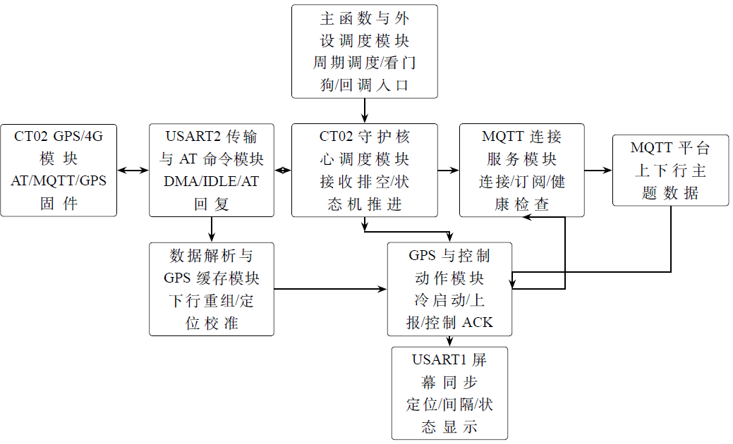
The USART2 daemon program can be abstracted in engineering implementation intothe main function scheduling layer, daemon interface layer, serial port transport layer, connection service layer, business action layer, and data parsing layer.The main function scheduling layer is responsible for driving tasks periodically; the serial port transport layer handles USART2 transmission and reception and AT command timing; the connection service layer maintains the CT02 in an MQTT online state with downlink topics subscribed; the business action layer executes GPS start/stop, status query, interval setting, and snapshot reporting; the data parsing layer converts module output into GPS samples and control results recognizable by the platform.
| Program Modules | Main Responsibilities |
|---|---|
| Main Function and Peripheral Scheduling Module | Initializes USART2, DMA, ADC, and USART1; periodically drives the CT02 daemon task in the main loop; implements USART2 DMA reception startup, IDLE interrupt flushing, error recovery, and a 1.5-second link watchdog; simultaneously forwards CT02-reported samples to the USART1 screen refresh. |
| Daemon Interface and State Context Module | Defines the daemon context, GPS samples, AT state, publish state, action state, topic cache, downlink queue, and statistical counters; also defines key parameters such as buffer size, reconnection backoff, and downlink reassembly timeout. |
| CT02 Guardian Core Scheduling Module | Provides guardian initialization, serial port binding, byte reception queuing, and periodic scheduling entry; each cycle proceeds in the order of "byte reception, AT driver activation, publish driver activation, action driver activation, and service state machine driver activation." |
| USART2 Transmission and AT Command Module | Encapsulates USART2 transmission, prioritized DMA transmission, and fallback blocking transmission; encapsulates AT command initiation, response collection, prompt transmission, and timeout termination. |
| MQTT Connection Service Module | Maintains the long-term online status of CT02, including AT port probing, MQTT status query, reconnection, downlink topic subscription, downlink queue processing, triggering periodic reporting, and regular health checks. |
| GPS and Control Action Module | Executes business actions, including GPS cold start at power-on, periodic GPS reporting, status query, GPS start/stop, setting reporting intervals, single snapshot, and error ACK for unsupported commands. |
| Data Parsing and GPS Cache Module | Provides string processing, lightweight JSON field parsing, MQTT topic construction, +MSUB downlink reassembly, GPS/NMEA parsing, positioning quality filtering, and latitude/longitude correction. |
USART2 Hardware Configuration and Reception LinkUSART2 is configured as the dedicated serial port for CT02, with a baud rate of 115200, 8 data bits, 1 stop bit, no parity, and no hardware flow control. Pin-wise, PA2 is connected to USART2_TX, and PA15 is connected to USART2_RX; DMA1_Channel5 is used for USART2_RX in circular reception mode with a priority of DMA_PRIORITY_VERY_HIGH; DMA1_Channel4 is used for USART2_TX in normal transmission mode with a priority of DMA_PRIORITY_MEDIUM. Both the USART2 interrupt and DMA channel interrupts are enabled, allowing the serial port guardian to utilize DMA half-full, DMA full, and USART idle interrupts to promptly retrieve module output.
After power-on initialization is completed,CT02_Guard_AppInit the function CT02_Guard_StartDmaRx is called first to start USART2 DMA circular reception. This function first stops the old DMA, then re-invokes HAL_UART_Receive_DMAwith a 128-byte buffer, and subsequently enables the USART2 IDLE interrupt. The IDLE interrupt is identified in USART2_IRQHandler : when UART_FLAG_IDLE is detected, the code clears the IDLE flag and calls CT02_USART2_IdleHandler, ultimately entering CT02_Guard_DmaRxDrainThis function calculates the current write position based on the DMA remaining count, and sequentially feeds all new bytes from the last read position to the current position into the processing routine. ct02_guard_on_rx_byte。
This approach of "DMA circular buffer with IDLE drain" is suitable for the AT module. The response from CT02 may be either short OK、ERRORor relatively long +MSUB downlink JSON and NMEA positioning statements. DMA avoids triggering the main program for every single byte, while the IDLE interrupt can promptly retrieve any residual bytes after a response ends. If DMA initialization fails, the program falls back to single-byte interrupt reception; HAL_UART_Receive_ITif an error occurs on USART2,HAL_UART_ErrorCallback it will restart DMA or interrupt reception and set a retry time of 100 milliseconds. This fallback logic ensures that the serial port daemon does not permanently fail due to a single DMA startup failure.
Upon entering ct02_guard_on_rx_byte , the bytes are not immediately parsed for business logic but are written into a 256-byte ISR ring buffer. When the main loop calls ct02_guard_tick ,ct02_drain_rx the bytes in the ring buffer are then segmented into lines according to \r or \n and passed to ct02_process_line. The line buffer has a length of 512 bytes; any data exceeding this length is counted in serial_rx_overflow and the current line is discarded. This layer isolates "interrupt-safe byte reception" from "potentially complex AT/GPS/MQTT parsing," reducing the risk of handling strings and JSON within interrupts.
MCU initialization during the power-on phase: After the device is powered on,main the function first executes HAL_Init and SystemClock_Config, then initializes GPIO, DMA, USART1, USART2, and ADC in sequence. After USART2 initialization is completed,CT02_Guard_AppInit begins to establish the CT02 daemon context. The default device ID provided in the current project is ct02-001The default GPS reporting interval is 10 seconds; if a valid interval value has been previously stored in the Data EEPROM, the EEPROM value shall take precedence. The health check interval is 30 seconds, the maximum number of GPS snapshot attempts is 30, the GPS active query interval is 30 seconds, and the MQTT connection uses a non-clean session with a keepalive interval of 60 seconds.
ct02_guard_init These configurations will be copied into the context, with boundary constraints applied: the reporting interval is limited to between 10 and 65535 seconds, the health check interval is limited to between 5 and 3600 seconds, and both the snapshot count and the GPS query interval are also constrained within a controllable range. The state machine then transitions to CT02_SERVICE_WAIT_AT, awaiting subsequent AT probing.gps_enabled The initial value is set to 1, indicating that the daemon program assumes by default that the GPS should be in the enabled state.
AT probing, MQTT connection, and topic subscription: The service state machine guarded by CT02 is driven forward by ct02_service_drive and ct02_service_on_done . The initial state is CT02_SERVICE_WAIT_AT, and the program sends a ATapproximately every 500 milliseconds. OK does the code enter the daemon mode:guard_mode is set to 1,boot_ready is set to 1, the MQTT connection flag and subscription flag are cleared, the reconnection backoff is reset to 3 seconds, and four topics are generated based on the device ID:
- Downlink control:
ct02/<deviceId>/down - Control acknowledgment:
ct02/<deviceId>/ack - Status report:
ct02/<deviceId>/up - Location report:
ct02/<deviceId>/gps
After entering the daemon mode, the state machine first sends a AT+MQTTSTATU to query the MQTT connection status. If the response indicates that the connection is already established, the program proceeds to subscription checking; if not connected, it sends a AT+MCONNECT=0,60. If the connection fails,ct02_service_mconnect_backoff the reconnection delay is increased exponentially from 3 seconds, with a maximum limit of 30 seconds, to avoid continuously sending AT commands at a high rate during network anomalies. After the MQTT connection is confirmed, the program sends AT+MSUB? Read the current subscription list; if the reply already contains the downlink topic of this device,subscription_ok set it to 1, and the state machine enters CT02_SERVICE_READY; otherwise, execute AT+MSUB="ct02/ct02-001/down",0 subscribing to the downlink control topic.
| State Phase | Function |
|---|---|
WAIT_AT | Send AT Detect whether the serial port and the CT02 AT firmware are available; upon receiving OK , the system enters the daemon mode. |
ENSURE_MQTT_QUERY | Send AT+MQTTSTATU Check whether MQTT is connected; this serves as the health check entry point of the service state machine. |
ENSURE_MQTT_CONNECT | Send AT+MCONNECT=0,60 Initiate an MQTT connection; upon failure, retry with a backoff interval ranging from 3 to 30 seconds. |
ENSURE_SUB_QUERY | Send AT+MSUB? Check whether the downlink topic has been subscribed. |
ENSURE_SUB_SET | Send AT+MSUB="ct02/ct02-001/down",0 Subscribe to the platform's downlink control topic. |
READY | Handle GPS initialization at startup, downlink queue, local interval modification, periodic GPS reporting, and periodic health checks. |
GPS Cold Start and Positioning Quality Filtering: When the service state machine first enters READY, it checks startup_cold_start_done. As long as a cold start has not been performed at startup and no AT command, publishing task, or business action is currently occupying the channel, it initiates CT02_ACTION_STARTUP_COLD. The cold start command sequence in the current source code is as follows: first, send AT+PWRM=1 to ensure that the CT02 is in normal power/working mode; then send AT+AGNSSGET=pos.asrmicro.com to obtain auxiliary positioning data, and then send AT+AGNSSSET Write the A-GNSS data into the module; then transmit. AT+MGPSGET=ALL,1 Have the module output complete GPS/NMEA related information; then first use AT+MGPSC=0 Close GPS, then use AT+GPSMODE=3 Set the GPS mode, and finally use AT+MGPSC=1 Re-enable GPS.
GPS cold start also incorporates a positioning quality threshold. The common module defines a 90-second cold start stabilization period, a minimum of 6 satellites, a maximum HDOP of 2.5, and requires 3D positioning. After parsing +GPSST, RMC, or GGA,ct02_cache_push_sample the system first appends the most recent NMEA quality information, then performs normalization. If the system is still within the cold start stabilization period, the NMEA mode is not autonomous positioning, the GGA positioning quality is invalid, the GSA is not 3D positioning, the number of satellites is insufficient, or the HDOP is too large, the sample will be marked as invalid positioning and will not be directly used as a platform trajectory point. This prevents the module from reporting drifting coordinates, zero-point coordinates, or weak-signal coordinates as true trajectories immediately after power-on.
AT command execution and serial port transmission protection: All AT commands are ct02_at_start used to create a unified state. This function appends the command string \r\n before transmission, and records the command owner, tag, timeout duration, and whether to wait for a prompt. The daemon divides AT commands into three owners: the service state machine, business actions, and MQTT publishing. Only one AT state is allowed to be active at any given time, thereby avoiding scenarios such as AT+MQTTSTATU query and AT+MPUB publishing simultaneously contending for the same USART2 channel.
USART2 transmission preferentially uses TX DMA. If the current UART is still in BUSY_TX or BUSY_TX_RX, the transmission function returns "retry later," and the state machine continues on the next tick; if DMA transmission fails, it falls back to HAL_UART_Transmit blocking transmission with a timeout of 300 milliseconds. For short JSON payloads that can be accommodated by a regular AT+MPUB , the code escapes the payload and directly places it into the command; if the payload is too long or contains characters unsuitable for direct embedding, it switches to AT+MPUBEX, first sending a command with the length, waiting for the module to return a > prompt, and then sending the raw payload. On the receiving path, ct02_guard_on_rx_byte Specifically identifies this > prompt to avoid processing it as a regular text line.
GPS positioning parsing, caching, and coordinate correction: The positioning information received via USART2 has two parsing paths. The first is the one native to CT02 +GPSST text, whose format includes positioning status, signal value, longitude, altitude, and latitude. The code ct02_parse_gpsst_line converts it into ct02_gps_sample_t. The second path is the standard NMEA sentence,ct02_parse_nmea_line supporting RMC and GGA: RMC is used to read the validity flag, latitude/longitude, and UTC date/time; GGA is used to read positioning quality, number of satellites, latitude/longitude, and altitude. The degree-minute format of NMEA is ct02_nmea_to_decimal converted to decimal degrees.
In addition to the direct positioning values,ct02_note_nmea_quality quality indicators are also extracted from GGA, GSA, and RMC, including GGA positioning quality, number of satellites, number of satellites used in positioning from GSA, GSA positioning dimension, HDOP, and the RMC mode character. Since these quality sentences and positioning sentences may not appear on the same line, the program retains the quality information for 15 seconds. As long as the time of a new sample is sufficiently close to the quality record, the quality fields are appended to the new sample.
Before a sample enters the cache, coordinate normalization is performed. Samples with no positioning, out-of-range coordinates, zero coordinates, or those failing the quality threshold are converted to fixStatus=0, with latitude and longitude cleared, and stored in latest_any ; samples that pass the filter are stored with their original WGS84 coordinates in rawLatWgs84 and rawLngWgs84, and then an engineering calibration offset is applied: the latitude offset is -0.0025458608, and the longitude offset is 0.0045950152. The corrected samples are written to latest_validfor periodic reporting, status queries, snapshot responses, and screen refresh. Therefore, the lat/lng displayed on the platform are the coordinates after this engineering calibration, while the original module coordinates are still retained in the payload for subsequent traceability.
Periodic reporting and MQTT publishing payloadIn the READY state, when the current time exceeds next_report_ms and no other action occupies the channel, the service state machine initiates a periodic action. The periodic action consists of two steps: first, publish to the GPS topic gps.report, then publish to the up topic gps.status. The GPS report contains type、source、ts、fixStatus、lat、lng、alt、cn、coordSystem、rawLatWgs84、rawLngWgs84 and reason. The status report includes the action source, the current reporting interval, the GPS switch status, and whether a valid position fix is available.
The periodic reporting sampling logic selects among the latest valid position fix, the most recent arbitrary position fix, and a placeholder sample indicating no position fix. If GPS is enabled and the latest valid sample is still within the time window, the reason field is periodic_fix; if there is no valid position fix but an arbitrary sample exists recently, a result of no position fix is reported with periodic_no_fix; if GPS is turned off, a no-position-fix sample with source guard.periodic.disabled is constructed. The valid time window is not a fixed value but is set to the larger of 60 seconds and three times the reporting interval, to prevent the previous valid position fix from being considered expired prematurely when the reporting interval is increased.
Platform downlink command processing: Platform downlink commands enter the CT02 module through the down topic of this device, and the module then outputs from USART2 +MSUB lines. Since +MSUB may place the topic, payload length, and JSON payload on the same line, or split them into multiple lines due to serial port segmentation,ct02_msub_consume_line implements lightweight reassembly: first, parse the topic and expected payload length; if the payload is incomplete, continue receiving subsequent ordinary text lines; if the payload is not completed within 2 seconds, or a new +MSUB、OK、ERROR, NMEA, or other non-continuation line is encountered, the reassembly fails and is counted in the packet loss statistics. After successful reassembly, the downlink packet enters a queue of length 2, waiting to be processed by the service state machine in the READY phase.
The currently supported control types revolve around gps.control . If type indicates a ping or link test, the device replies with connectivity results; if type=gps.control, the selection is made based on action . status、enable、disable、set_interval or snapshotEach action extracts requestIdIf the payload is not provided, a fallback sequence number is generated at the time of reception to ensure that the platform can correlate the ACK with the downlink request.
| Action | MCU-side processing |
|---|---|
ping | First, publish a reception acknowledgment to the ACK topic, then return either a pong or the test message from the payload to the up topic for platform link probing. |
status | Publish a received ACK, wait for a configurable probing window, and query AT+MGPSC? and AT+GPSMODE?Then report the heartbeat, GPS switch, GPS mode, number of cached rows, current interval, and valid positioning status, and finally publish a done ACK. |
enable | Publish received and running ACKs, execute the AT command sequence related to GPS startup, probe the output after startup, and then publish one GPS report, one status report, and a done ACK. |
disable | Publish a received ACK, execute AT+MGPSC=0 Close GPS, construct a positioning report with no valid fix, publish a status update, and return in the done ACK whether the GPS was successfully closed. |
set_interval | put intervalSeconds Constrained between 10 and 65535 seconds, update report_interval_s and next_report_msPublish the interval_updated status and a done ACK with the new interval. |
snapshot | Publish received and running-phase ACKs, first check whether a GPS heartbeat already exists; if silent and a cold start is allowed, execute the GPS startup command, then query multiple times according to the configured interval AT+GPSSTFinally, publish a single GPS report, status, and done ACK. |
Anomaly Recovery and Guardian ReliabilityThe USART2 guardian has two layers of recovery mechanisms. The first layer is serial link recovery: the recovery check function in the main loop checks whether reception is in the armed state; if DMA or interrupt-based reception has not started, it attempts to restart DMA reception every 100 milliseconds, falling back to single-byte interrupt reception upon failure. The second layer is service state recovery: in the READY state, if mqtt_connected becomes 0, the state machine clears the subscription flag and immediately returns to the MQTT state query; if publishing fails, the action layer considers the MQTT link unavailable and actively switches the service phase to reconnection. The reconnection backoff is constrained between 3 and 30 seconds, allowing automatic reconnection after network recovery while preventing the AT port from being overwhelmed by continuous retries in weak network environments.
In addition, the main function and peripheral scheduling module implement a 1.5-second software watchdog-style "guardian feeding" statistic. Each time a serial byte is received, a transmission is completed, or a critical state is processed, the guardian counter increments; the recovery check function periodically compares whether this counter has changed. If it remains unchanged for an extended period, a timeout flag is set, and the timeout count is accumulated in the next guardian cycle. The current code does not directly reset the MCU or CT02 upon timeout but instead uses it as a basis for runtime diagnostics and subsequent recovery strategies.
Serial Screen Display and Battery Level Detection
USART1 TJC Serial Screen Display and Local Control
USART1 is used to connect the TJC serial screen, handling the display refresh and parameter setting input for the local interface. It is independent of the CT02 daemon channel on USART2: USART1 is oriented towards the user interface, while USART2 is oriented towards the 4G/GPS module and the MQTT platform. This structure ensures that a screen refresh failure or a power loss of the screen does not directly disrupt the AT state machine of the CT02 module, and also facilitates treating the screen as a power-consuming peripheral that can be closed.
In the display direction, the STM32L0 generates variable commands for the serial screen based on the current operating state, for example, writing the platform access address, GPS reporting interval, positioning status, network status, and battery status to the corresponding controls. TJC screen commands are typically sent in text form and are terminated by three consecutive 0xFF characters. To reduce the probability of parsing errors on the screen, the firmware should ensure that "one control command corresponds to one UART transmission" and avoid concatenating multiple control updates into an excessively long serial packet.
In the input direction, the serial screen sends local settings back to the STM32L0 in a fixed frame format. The positioning interval setting frame can be abstracted as:
0x05 0x52 L H 0x26
where L and H forms a 16-bit little-endian integer, representing the new reporting interval in seconds. After receiving this frame, the microcontroller performs a range check and then updates the local timing variable. Simultaneously, this parameter can also be fed back to the MQTT platform via the USART2 path, ensuring consistency between the web console and the local screen. This forms a closed loop where "parameters can be modified via platform issuance or locally on the screen, are uniformly saved on the device side, and the status is reported back."

Lithium Battery Power Detection Design
Lithium battery detection utilizes the 12-bit on-chip ADC on PA3. In hardware, a single 3.7V lithium battery is divided by two 100kΩ resistors in series. The ADC sampling point is taken at the midpoint, so the voltage entering PA3 is approximately half of the battery terminal voltage. Let the pull-up resistor be \(R_1=100\,\mathrm{k\Omega}\), the pull-down resistor be \(R_2=100\,\mathrm{k\Omega}\), the ADC reference voltage be \(V_{\mathrm{REF}}\), and the 12-bit sampling code value be \(N\). Then:
$$V_{\mathrm{ADC}}=\frac{N}{4095}V_{\mathrm{REF}},\qquad V_{\mathrm{BAT}}=2\frac{N}{4095}V_{\mathrm{REF}}$$
When \(V_{\mathrm{REF}}=3.3\,\mathrm{V}\), this can be approximated as \(V_{\mathrm{BAT}}\approx \frac{6.6N}{4095}\). For example, when the ADC reading is \(N=2500\), the battery voltage is approximately \(4.03\,\mathrm{V}\).
The conversion from battery voltage to remaining capacity cannot be completely linear because the discharge curve of a lithium battery is relatively flat in the middle section and drops rapidly near the end. The program first uses a linear limiting model to obtain a basic percentage estimate:
$$\mathrm{SOC}_{\mathrm{lin}}=\mathrm{clip}\left(\frac{V_{\mathrm{BAT}}-3.30}{4.20-3.30}\times100\%,\,0,\,100\%\right)$$
where \(\mathrm{clip}(x,0,100\%)\) indicates that the result is constrained between 0 and 100\%, \(4.20\,\mathrm{V}\) is treated as full charge, and \(3.30\,\mathrm{V}\) is treated as the low-voltage cutoff.
To make the screen display more closely match the actual discharge characteristics of a single lithium battery, the capacity display is further processed using piecewise interpolation. The nodes are as follows:
| Battery Voltage / V | 3.30 | 3.50 | 3.65 | 3.75 | 3.85 | 4.00 | 4.20 |
|---|---|---|---|---|---|---|---|
| Estimated Capacity / % | 0 | 5 | 20 | 40 | 60 | 80 | 100 |
Since the total resistance of the two 100kΩ resistors in series is \(200\,\mathrm{k\Omega}\), the quiescent current of the voltage divider branch at full charge (4.2V) is approximately \(21\,\mathrm{\mu A}\), which is suitable for low-power devices. However, the equivalent source impedance of this divider network is approximately \(50\,\mathrm{k\Omega}\). During actual sampling, the ADC sampling time should be appropriately increased. If necessary, a small capacitor can be connected in parallel at the ADC input for low-pass filtering to reduce sampling errors and transient jitter caused by the high-impedance source.
Project Summary
This report focuses on the provincial-level university student innovation and entrepreneurship training program project titled "RF Micro-sensing Test System for Drug Efficacy." It completes the design, implementation, and verification of an IOT-MQTT full-stack IoT engineering Demo using GPS positioning data as the demonstration payload. This engineering effort is not an isolated GPS positioning system but a critical infrastructure for the IoT data reporting pathway within the overall project architecture. Its core objective is to establish an end-to-end data loop from the field device to the remote platform before the final calibration of the RF micro-sensor is completed, thereby verifying the feasibility and stability of the communication protocol, platform parsing logic, command control closed loop, and visualization framework. This provides a directly migratable engineering foundation for the subsequent integration of drug component analysis results.
On the platform side, this project built an integrated IoT server based on Node.js, encompassing an Aedes MQTT Broker, Express Web service, Socket.IO real-time channel, REST API, and SQLite local database. The platform implements functionalities including device identity authentication and topic constraints, multi-format GPS protocol parsing, device status persistence, full lifecycle tracking of command tasks, offline command queue retransmission, and real-time visualization on the web console. Through FRP intranet penetration and port mapping on an Alibaba Cloud public server, field 4G devices can connect to the platform from any area with cellular network coverage, verifying service availability under public network deployment conditions. The web console provides full status snapshots via REST interfaces and pushes incremental events via Socket.IO, enabling multi-dimensional real-time monitoring of device online status, GPS trajectories, message flows, and command results.
On the device side, the STM32L0 microcontroller, through the USART2 DMA circular reception and IDLE interrupt draining mechanism, constructs a highly reliable CT02 AT firmware daemon. This daemon drives the entire chain of business logic in a non-blocking state machine manner, including AT probing, MQTT connection maintenance, downlink topic subscription, GPS cold start and positioning quality filtering, periodic reporting, and parsing and execution of platform downlink commands. Concurrently, the system connects to a TJC serial screen via USART1 for local human-machine interaction, utilizes the PA3 ADC for lithium battery power detection, and implements "sleep/running" state switching via the PA4 external interrupt and PA5 screen power control. This effectively reduces static power consumption during unattended operation while ensuring uninterrupted background communication.
From the perspective of the overall project evolution, the greatest value of this engineering effort lies inArchitecture First, Data ReplaceableAt the current stage, the device end reports GPS coordinates via MQTT topics, the platform side parses and stores the data according to the established protocol, and the Web end renders trajectory points on the map. This complete process effectively validates and solidifies the topic naming conventions, payload JSON structure, command request-ACK closed-loop mechanism, offline retransmission strategy, and front-end visualization components. Once the subsequent RF micro-sensor completes the calibration of drug composition, it is only necessary to replace the sampling payload on the device end from GPS data to sensor analysis results (such as resonant frequency shift, dielectric constant change, or component concentration inversion values), and correspondingly extend the payload identification logic in the platform parsing module. This allows direct reuse of the existing topic system, database table structure, REST interfaces, and Web console framework, enabling remote real-time reporting, historical traceability, and anomaly warning for drug composition detection data.
In summary, this project has successfully constructed a fully functional, scalable, and low-power IoT data loop, serving both as a complete technical achievement for the "Integrated Project Practice" course and as an important engineering foundation for the provincial-level innovation project "RF Micro-Sensing Test System for Drug Efficacy" as it moves toward practical application scenarios. Subsequent work will focus on the precision calibration of the RF micro-sensor, the establishment of a drug sample library, and the optimization of composition analysis algorithms. At that time, the full-stack IoT architecture described in this report can directly carry sensor analysis data, assisting the project in ultimately achieving intelligent networked monitoring of drug efficacy.