
Summary of the Course: Principles and Applications of Microcontrollers
The learning path of this course progressed from microcontroller hardware, registers, and basic RAM operations to timer/interrupt, dynamic scanning of digital tubes, and DAC0832 waveform generation, ultimately culminating in the implementation of a comprehensive system featuring UART protocol and EEPROM power-off storage. It must be noted that some of the C51 code was generated by AI, primarily due to the limited resources of the 51 microcontroller, which significantly reduces the error rate for AI-generated code. However, the top-level design was still manually defined. Since I was preparing for the Electronics Design Contest during the fourth semester, I missed several of Professor Hu’s classes (especially those on microcontroller hardware). Although the content is not difficult for me now, Professor Hu taught with great enthusiasm and provided very clear explanations.The architectural knowledge of the 51 microcontroller also served as one of the foundations for the RISC-V project I completed in the fifth semester.Although I have now acquired basic knowledge of microcontroller hardware (e.g., power circuits, reset circuits), I still regret having missed those classes, as self-study is never as efficient as direct instruction from an excellent teacher.
Scope of Assignments and Learning Objectives
The course assignments progressed in a "from basic to comprehensive" order: starting with I/O and memory access, then moving to timer and interrupt design, followed by digital tube interaction and DAC waveform output, and finally completing multi-module integration through a physical system.
From the directory structure, Experiment Reports 1–5 collectively cover 14 individual experimental tasks,and in the final project, functional integration and protocol-based control were achieved, forming a complete training loop from "single-point functionality" to "system engineering."
Scale of Experiments
Experiment Reports 1–5 + Microcontroller Final Project, covering the core knowledge points of the course and the engineering practice pathway.
Toolchain
Primarily based on Keil C51 and Proteus simulation, supplemented by physical system debugging to complete key functional verification.
Core Competency Progression
GPIO Control → Timer/Interrupt → Dynamic Display and Key Input → DAC Waveform → UART + EEPROM System Integration.
Engineering Deliverables
Comprehensive materials have been produced, including LaTeX experiment reports, Keil projects, Proteus projects, and a GitHub code repository.
Overview of Experimental Stages
| Stage | Representative Experiment | Core Training Focus |
|---|---|---|
| Experiment Reports 1–2 (Introductory) | Data migration, single LED blinking, 8-bit running LED | On-chip/off-chip memory access, GPIO output, timer fundamentals, and delay control |
| Experiment Report 3 (Timing and Waveform) | 67ms fixed-period square wave, 1k/100/10/1Hz frequency switching, adjustable duty cycle | Timer 0 Mode 1, external interrupt triggering, frequency division, and duty cycle adjustment |
| Experiment Report 4 (Display and Interaction) | Seven-segment display showing "2024", key step control, 24-second countdown | Dynamic scanning, multi-key debouncing, display buffer, and state machine |
| Experiment Report 5 (Digital-to-Analog Conversion) | Sawtooth wave, triangular wave, custom waveform | DAC0832 driver, lookup table method, timer precise control of 67ms period |
| Major project (system integration) | Serial screen stopwatch physical system | UART protocol, mode switching, AT24C02 power-off storage and system integration debugging |
Learning Path:Summary of Key Experiments
Key point 1: From low-level resource access to basic control logic
In the "Data Migration" experiment, through xdata and idata completing the transfer of off-chip addresses 0x1000~0x1030 to on-chip 0x30~0x60 memory and clearing the original area, an intuitive understanding of the C51 memory space and address mapping was established.
Key point 2: Timer/interrupt-driven waveform control
In Experiment Report 3, a square wave output with a specified period (20 + last two digits of student ID, corresponding to approximately 67ms) and multi-frequency switching were completed using a 12MHz clock.
Key point 3: Digital tube dynamic scanning and key interaction
Experiment Report 4 gradually expanded from static digital display to key stepping and countdown control, with a focus on mastering bit-select/segment-select timing, key debouncing, and external interrupt triggering.
Key point 4: DAC0832 waveform generation and modular code structure
Experiment Report 5 completed the output of sawtooth, triangular, and custom waveforms, using the lookup table method and timer interrupt to control the sampling interval, with a measured period of approximately 67ms. getSawWave、getTriangleWave the separation of the lookup table and custom waveform table, a clearer functional and extensible design was achieved.
| Experiment module | Implementation result | Review key points |
|---|---|---|
| Square Wave Frequency Switching | Supports switching among 1 kHz / 100 Hz / 10 Hz / 1 Hz | Under 1 kHz, the ISR load is relatively high, requiring further optimization of the interrupt path |
| Duty Cycle Adjustment | Stable adjustment effect at low and intermediate frequencies | High-frequency scenarios require optimization of counting and reload strategies |
| 24-Second Countdown | Implements start/pause/reset and dynamic display | Time accuracy and pause-state interaction still have room for parameter tuning |
| DAC Waveform Output | Sawtooth wave / triangular wave / custom waveform output as expected | Sampling points and timing accuracy directly affect waveform smoothness |
Major Project: Serial Screen Stopwatch Physical System
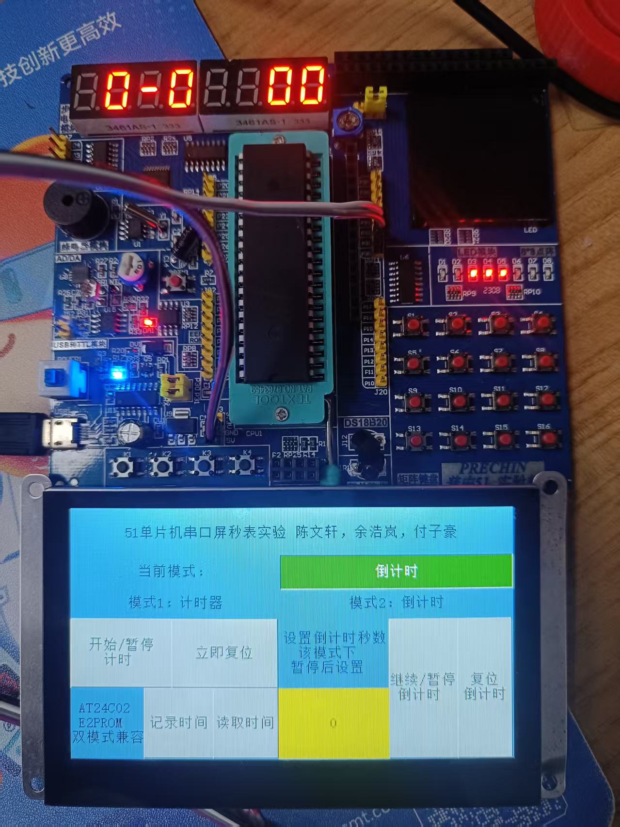
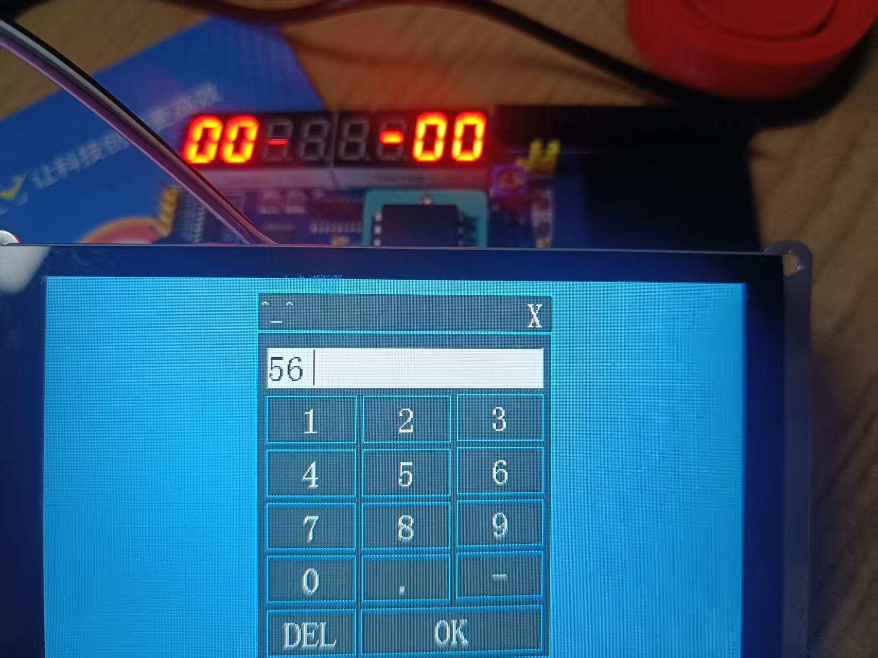
The major project fully integrates the core modules of the course: using the 51 microcontroller as the control core, combining digital tube display, serial screen command interaction, countdown state machine, and AT24C02 power-off storage, forming a deployable physical system.
Step 1: Timer/Countdown Dual Mode
Maintained by the main loop Min/Sec/MiniSec, with interrupt-driven time advancement and support for mode switching.
Step 2: UART Protocol Control
Adopts 0x05 frame header, command word, optional data field,0x26 Frame tail, enabling communication between the serial screen and the microcontroller.
Step 3: AT24C02 Power-Down Storage
Read and write minutes, seconds, and hundredths of a second via I2C, supporting the saving and restoration of current time data.
Step 4: Status Feedback and Integrated Debugging
When the countdown ends, an LED prompt is triggered. Combined with key presses and serial commands, the overall system functionality is verified.
Serial Command Examples:Course Achievements and Areas for Improvement
Enhanced Understanding of Low-Level Concepts
A more stable engineering intuition has been developed regarding the C51 memory regions, register configuration, bit operations, and timing control.
Establishment of Interrupt-Based Thinking
The ability to separate responsibilities between the main loop and interrupts has been achieved, reducing the impact of blocking logic on real-time performance.
System Integration Capability
Multi-module coordination and integrated debugging have been realized, including display, keypad, serial communication, EEPROM, and LED indication.
Awareness of Continuous Optimization
Frequency errors and interaction boundary issues were proactively documented in the report, clarifying directions for subsequent optimization.
Preview of Core Results
Below is a physical image of the serial screen stopwatch, providing an intuitive view of the overall system setup.
Open-Book Exam Sheet
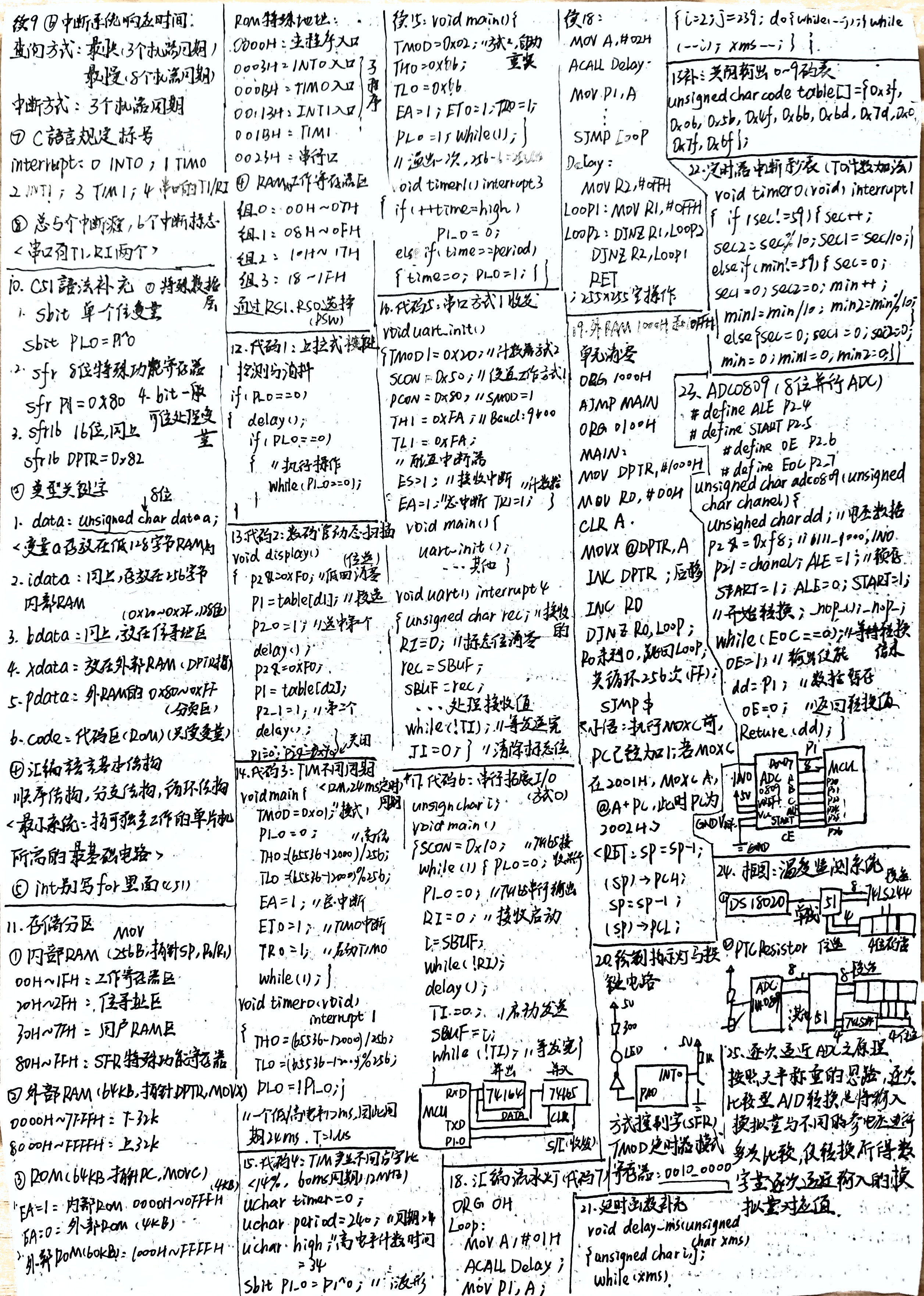
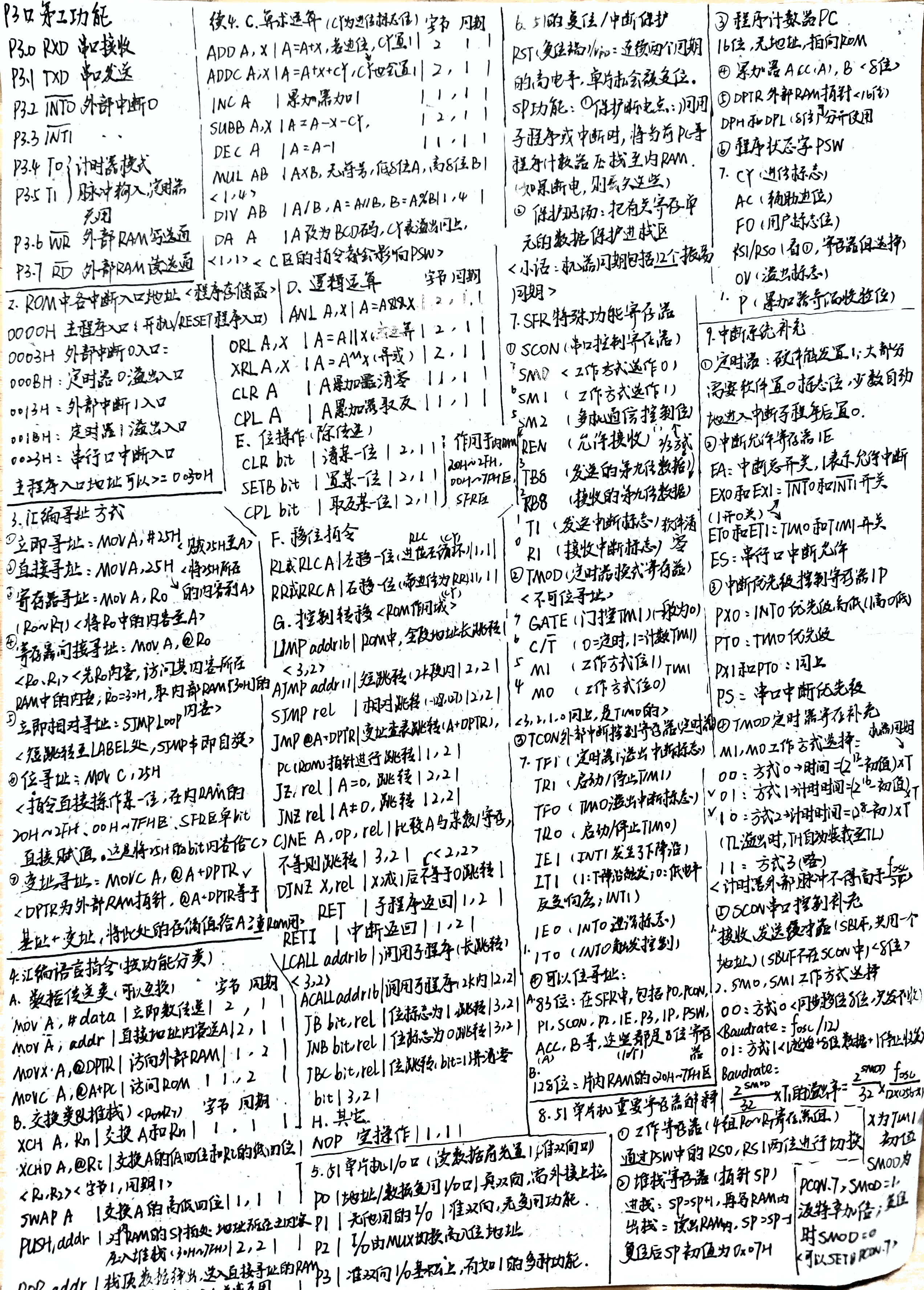
The one-page open-book reference sheet used in the course final exam is organized as follows, including both the front and back sides. Click on the images to enlarge and view details.
Open the front side of the original image Open the reverse side of the original image
GitHub Repository
ChrisChan114514/HDU-HC-OSP-Principle-and-application-of-MCU
Open-source repository for experiments on Microcontroller Principles and Applications